Ever-Power Co., Ltd.
Email: [email protected]
Product displayProduct Display
- Coupling
- Small flexible coupling
- Pulley
- gear
- rack
- Sprocket
- Spiral bevel gear
- Bevel gear
- Worm Gear
- Expansion coupling sleeve
- Torque limiter
- Timing belt
- Pulley
- Cone sleeve embedded pulley
Contact information
gear
product manual
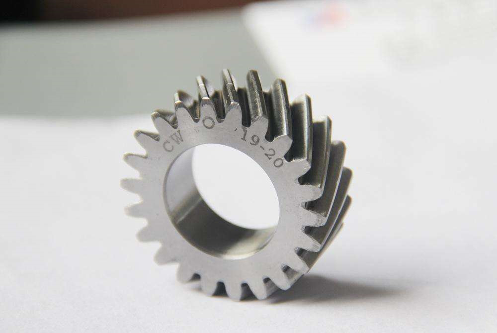
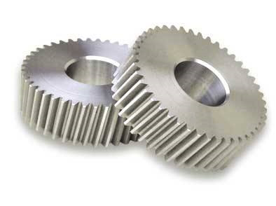
what ishelical gear
Helical gear (helical gear) is not exactlyHelical gearIt should be said that the helical gear is the meshing method of two helical gears, which is distinguished by the different directions in which they transmit force in space.Ordinary spur gears enter at the same time along the tooth width啮Together, Resulting in shock, vibration and noise, and uneven transmission.Helical toothcylindergearTransmission is better than straight teeth, and can be tight中Heart distanceUsed for high-speed heavy loads. helical gearReducerIt is a novel reduction transmission device.Adopting the most optimized and advanced design concept of modular combination system, it has small size, light weight, large transmission torque, stable starting, fine transmission ratio classification, and can be connected at will and a variety of installation positions can be selected according to user requirements.
Helical gear parameters

斜gearArt style
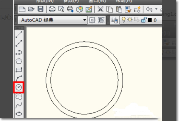
1. cadhelical gearThe drawing method is very simple. First, open the CAD orthogonal mode, and open the center capture, nearest point capture and end point capture of CAD.

2. Next, use the cad circle command to draw a concentric circle.
3. Use the CAD line tool to draw a gear on the outer circle.

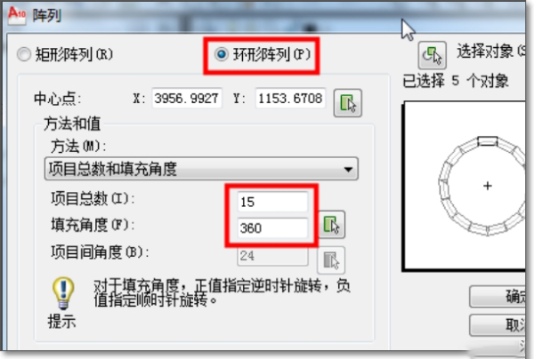
4. Select the circular array in the cad array, and enter the number and angle of the array as 360 degrees.
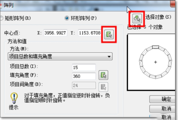
5. Next, click the arrow icon in the array to set the center point of the array as a concentric dot, and select the gear just drawn. (Remember to check the rotate item when copying)
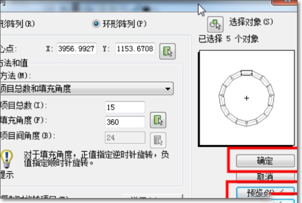
6. After setting the cad array, you can click preview first, and then press Enter to return and click OK.
7. At this time, a cadhelical gearIt's basically done
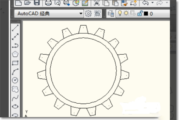
8. Finally, we use the cad trim tool to delete the extra lines on the outer circle, cadhelical gearThe painting method is complete.
Recommended Products