Product Description
Product Description
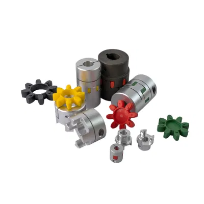
QZM-82 CNC machining small parts
1. Precision CNC machining parts strictly follow customers’ drawing, packing, and quality requirements.
2. Tolerance: between+/-0.01mm;
3. The high-tech CMM inspector to ensure the quality;
4. Full-Experienced engineers and well professional trained workers;
5. Fast delivery time;
6. Professional advice for our customers;
Detailed Photos
Product Parameters
Our advantage of cnc machining:
| Business Type | Beyond the Manufacturer and strong organized ability in the industrial |
| Benefits | 1. Deeper industrial experience at CNC machining parts service for more than 10-years,our customer’s requirement is our 1st priority. 2. 2D or 3D files is available; 3. We trust the quality priority and we insist the good quality should be based on the customers’ satisfied; 4. Without any MOQ requirement; 5.Faster delivery time; 6. Customized size and specification /OEM available 7. Near ZheJiang Port |
The material
| Materials Accept |
Stainless Steel | SS201, SS303, SS304, SS316 etc. |
| Steel | Q235, 20#, 45#, | |
| Brass | C36000 ( C26800), C37700 ( HPb59), C38500( HPb58), C27200(CuZn37) , C28000(CuZn40) | |
| Iron | 1213, 12L14,1215 etc. | |
| Bronze | C51000, C52100, C54400, etc. | |
| Aluminum | Al6061, Al6063,AL7075,AL5052 etc | |
| Plastic | ABS,POM,PC(Poly-Carbonate),PC+GF,PA(nylon),PA+GF, PMMA(acrylic)PEEK,PEI etc) |
Packaging & Shipping
- We prefer DHL or TNT express or other air freight between 1kg-100kg.
- we prefer sea freight more than 100kg or more than 1CBM
- As per customized specifications.
Company Profile
About us
HangZhou CZPT Technology Co.,Ltd is located in HangZhou City, ZheJiang Province, Which closed the ZheJiang .The Emitech Technology is mainly engaged in the CNC Machinery Industrial Service for 15 years. Our Parts are sold to Europe, America, Japan, South Korea and China in various kinds of industrial.At present, Our company has CNC Turning machines and CNC centers and equip with professional quality and testing instruments.We have full OEM Experience from worldwide, providing them with One-stop solutions for a broad range of applications.We look CZPT to cooperating with you!
Our Advantages
1. Precision CNC machining parts strictly follow customer’s drawing,packing and quality requirement.
2. Tolerance: between+/-0.01mm;
3. The high-tech CMM inspector to ensure the quality;
4. Full-Experienced engineers and well professional trained workers;
5. Fast delivery time;
6. Professional advice for our customers;
After Sales Service
CNC machining prototype design rapid prototyping
We usually provide 12 Months repair service. If our duty, we will respond to send the new parts.
Our Service
| Our Processing | CNC center, CNC milling, CNC turning, drilling, grinding, bending, stamping, tapping, |
| Surface finish | Polishing, sandblasting, Zinc-plated, nickel-plated, chrome-plated, silver-plated, gold-plated, imitation gold-plated, |
| Tolerance | 0.05mm~0.1mm |
| QC System | 100% inspection before shipment |
| Drawing format | CAD / PDF/ DWG/ IGS/ STEP |
| Packaging | Plastic bag/Standard package / Carton or Pallet / As per customized specifications |
| Payment Terms | 30 -50%T/T in advance, 70-50% balance before delivery; Pay Pal or Western Union is acceptable. |
| Trade terms | EXW, FOB, CIF, As per the customer’s request |
| Shipment Terms |
1)We prefer DHL or TNT express or other air freight between 1kg-100kg. 2) we prefer sea freight more than 100kg or more than 1CBM |
| Note | The CNC machining parts are usually custom-made based on the customer’s drawings and samples. So we need the Down Payment |
Are there any industry standards or guidelines for designing and using spider couplings?
Yes, there are industry standards and guidelines that provide recommendations for designing, selecting, and using spider couplings in various mechanical systems. These standards help ensure the safe and reliable operation of spider couplings in industrial applications. Some of the relevant standards include:
- AGMA 9002-B15: This American Gear Manufacturers Association (AGMA) standard provides guidelines for the selection and application of flexible couplings, including spider couplings. It covers topics such as coupling types, misalignment, torque capacity, and lubrication.
- ISO 14691: This International Organization for Standardization (ISO) standard specifies methods for testing the torsional stiffness of flexible couplings, including spider couplings. It outlines procedures for determining the dynamic torsional stiffness and related parameters.
- API 671: This American Petroleum Institute (API) standard provides guidelines for special-purpose couplings used in petroleum, chemical, and gas industry services. It covers design, manufacturing, inspection, and testing requirements for couplings, including those with elastomeric elements.
While these standards offer valuable insights, it’s important to note that specific industry requirements and applications may influence the design and selection of spider couplings. Manufacturers, engineers, and designers should also consider factors such as torque, misalignment compensation, environment, and system dynamics when applying these standards to their designs. Adhering to industry standards ensures that spider couplings are properly designed, installed, and used to meet the intended performance and safety criteria.
What are the symptoms of spider coupling wear or deterioration, and how can they be identified?
Spider couplings, like other mechanical components, can experience wear and deterioration over time due to factors such as torque, misalignment, and environmental conditions. Identifying the symptoms of wear is crucial for maintaining coupling performance and preventing unexpected failures. Here are some common symptoms of spider coupling wear and deterioration:
- Vibration and Noise: Increased vibration or unusual noise during operation can indicate wear in the spider coupling. Excessive wear can lead to reduced dampening of vibrations and increased noise levels.
- Reduced Torque Transmission: If the coupling is no longer transmitting torque efficiently, it may indicate wear or damage to the elastomeric spider. Reduced torque transmission can result in decreased equipment performance.
- Visible Cracks or Tears: Inspect the elastomeric spider for visible cracks, tears, or signs of deformation. These issues can lead to uneven load distribution and compromised coupling function.
- Uneven Shaft Movement: Misalignment caused by wear can lead to uneven movement of connected shafts. This can be observed through irregular motion or wobbling during operation.
- Increased Heat Generation: If the coupling is generating more heat than usual, it may indicate excessive friction due to wear. Overheating can accelerate wear and affect coupling performance.
- Irregular Performance: If machinery or equipment connected by the coupling experiences irregular or unpredictable behavior, it could be a sign of coupling wear affecting torque transmission.
To identify these symptoms, regular visual inspections, vibration analysis, and performance monitoring are recommended. If any of these symptoms are observed, it’s advisable to replace the worn or damaged spider coupling with a new one. Routine maintenance and timely replacement can help ensure the continued reliability and performance of spider couplings in mechanical systems.
How do you properly install and maintain a spider coupling in machinery?
Installation:
Proper installation of a spider coupling is essential to ensure its optimal performance and longevity. Here are the steps for installing a spider coupling:
- Ensure Safety: Before starting any installation, make sure the machinery is properly shut down and all energy sources are disconnected.
- Inspect Components: Check the hubs, elastomeric spider, and shafts for any damage or debris. Ensure that the components match the correct specifications.
- Align Shafts: Align the shafts to minimize initial misalignment before inserting the elastomeric spider.
- Insert Spider: Place the elastomeric spider into one of the hubs, ensuring that the lobes or fins are correctly aligned with the grooves in the hub.
- Align Second Hub: Carefully align the second hub with the first one, making sure the spider lobes fit into the grooves of both hubs.
- Press Hubs Together: Gently press the hubs together until they meet. Avoid using excessive force, as this could damage the elastomeric spider.
- Check Alignment: After installation, check the alignment of the shafts and the coupling. Misalignment should not exceed the manufacturer’s recommended limits.
- Tighten Fasteners: Tighten the fasteners on the hubs according to the manufacturer’s torque specifications. Use a torque wrench to ensure proper tightening.
- Verify Clearance: Check for proper clearance between the coupling and surrounding components to prevent interference during operation.
- Run System: Start the machinery and monitor the coupling for any unusual vibrations or noise. Make any necessary adjustments if issues are detected.
Maintenance:
Maintaining a spider coupling is important to ensure its continued performance and prevent premature failure. Here are some maintenance tips:
- Regular Inspection: Periodically inspect the spider coupling for signs of wear, damage, or deterioration. Look for cracks, tears, or other abnormalities in the elastomeric spider.
- Clean Environment: Keep the coupling and surrounding area clean from dirt, debris, and contaminants that could impact its performance.
- Lubrication: Spider couplings are self-lubricating due to the elastomeric material. Avoid using additional lubricants, as they can deteriorate the elastomeric properties.
- Temperature Consideration: Be aware of the temperature range specified by the manufacturer for the elastomeric material. Extreme temperatures can affect the performance and lifespan of the coupling.
- Replace Worn Parts: If the elastomeric spider shows signs of wear, replace it with a new one from the manufacturer. Do not continue using a worn or damaged spider.
- Monitor Vibrations: Regularly monitor the machinery for unusual vibrations or noise, as these can indicate issues with the coupling. Address any problems promptly.
- Follow Manufacturer Guidelines: Adhere to the manufacturer’s recommended maintenance schedule and guidelines for the specific spider coupling model.
Proper installation and regular maintenance contribute to the reliable and efficient operation of a spider coupling in machinery.


editor by CX 2023-08-18
China manufacturer Lovejoy Standard L090 Jaw Spider Coupling
Product Description
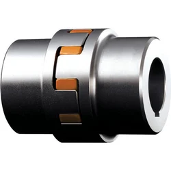
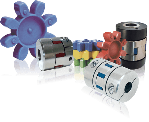
SYPT L090 Jaw Type couplings are offered in the industry’s largest variety of stock bore/keyway combinations.
These couplings require no lubrication and provide highly reliable service for light, medium, and heavy duty electrical motor and internal combustion power transmission applications.
Now we provide 3 different kinds of the inserts,rubber,urethane and hytrel,color can be made to order..
For the hubs,commom material is GG25 and aluminum.
Please contact us to learn more.
ZheJiang shine transmission machinery Co., Ltd is specialized in manufacturing and selling transmission products. Our products are exported to the world famous machinery company in Europe, America, South Africa, Australia, southeast Asia etc.
Our main products include: European pulley, American pulley, couplings, taper bushing, qd bush, lock element, adjustable motor base, motor rail, sprockets, chain, bolt on hubs, weld on hubs, jaw crusher equipment & spare parts and all kinds of non-standard Casting products etc.
The good quality of our products is demonstrated in various machinery equipment. For example, mining equipment, grain equipment, fan, air compressor, vacuum pump, woodworking machinery, papermaking machinery, mixing equipment etc.
Our slogan is”qualified products win customers, good service benefits customers”. By establishing a closer cooperation with old and new clients, We’ Ll be able to guarantee a CZPT situation develop and progress together.
Could you provide examples of industries or applications where spider couplings are commonly used?
Spider couplings find application in a wide range of industries and mechanical systems where torque transmission, misalignment compensation, and vibration dampening are important. Here are some examples of industries and applications where spider couplings are commonly used:
- Manufacturing: Spider couplings are used in various manufacturing equipment, including conveyor systems, packaging machinery, and CNC machines. They help transmit torque between motors and shafts while accommodating misalignment.
- Agriculture: Agricultural equipment such as tractors, combines, and harvesters often use spider couplings to connect and transmit power between different components.
- Automotive: Spider couplings can be found in automotive applications, including drive shaft connections and steering systems, where they help transfer torque and accommodate movement.
- Pumps and Compressors: Spider couplings are used in pumps and compressors to connect motors to impellers or rotors, ensuring efficient torque transmission and vibration isolation.
- Material Handling: Material handling systems, including conveyors, elevators, and cranes, use spider couplings to connect various components and transfer torque.
- Printing and Packaging: Spider couplings are used in printing presses, packaging machines, and labeling systems to ensure precise torque transmission and compensate for misalignment.
- Textile Machinery: Textile manufacturing equipment such as spinning machines and looms utilize spider couplings to connect drive components and transmit power efficiently.
- Food and Beverage: Spider couplings are used in food processing equipment and beverage production lines, where they provide sanitary and reliable torque transmission.
These examples illustrate the versatility of spider couplings in various industries and applications. Their ability to handle torque transmission, misalignment compensation, and vibration reduction makes them a practical choice for a wide range of mechanical systems.
Can you explain the concept of torsional stiffness in relation to spider couplings?
Torsional stiffness is a crucial concept in the design and functionality of spider couplings. It refers to the ability of a coupling to resist rotational deformation (twisting) when subjected to a torque load. In other words, torsional stiffness measures how much a coupling can maintain its shape and transmit torque without excessive twisting or deformation.
In the context of spider couplings:
- High Torsional Stiffness: A coupling with high torsional stiffness exhibits minimal angular deflection or twisting when torque is applied. This ensures accurate torque transmission and precise alignment between connected shafts. High torsional stiffness is especially important in applications that require accurate positioning and synchronization.
- Low Torsional Stiffness: A coupling with low torsional stiffness allows for some degree of angular misalignment between shafts and can accommodate slight variations in torque load. This flexibility can be advantageous in applications where misalignment or shock absorption is necessary.
When selecting a spider coupling for a specific application, the torsional stiffness of the coupling needs to be considered based on the requirements of the machinery system. The choice between high and low torsional stiffness depends on factors such as the level of precision needed, the type of load, the degree of misalignment, and the overall performance objectives.
It’s important to note that while torsional stiffness is a key consideration, other factors like the material of the elastomeric spider, size of the coupling, and the type of spider profile also play a role in the coupling’s overall performance and behavior.
Are there different types of spider couplings available for various uses?
Yes, there are different types of spider couplings available to suit various industrial applications and requirements. These variations in design and material offer flexibility in choosing the right coupling for specific uses. Here are some common types of spider couplings:
- Standard Jaw Couplings: These couplings feature a simple design with two hubs and an elastomeric spider. They are suitable for general-purpose applications that require misalignment compensation and torque transmission.
- Curved Jaw Couplings: These couplings have curved lobes on the elastomeric spider, allowing for increased misalignment compensation and dampening of vibrations. They offer higher torque capacity and are commonly used in pumps, compressors, and conveyors.
- Spider Couplings with Spacer: These couplings include a spacer between the hubs, allowing for greater axial misalignment compensation. They are used in applications with longer distances between shafts.
- Lovejoy Couplings: Lovejoy couplings are a specific brand of spider couplings known for their high torque capacity, durability, and ease of installation. They come in various styles, including standard, curved jaw, and split type.
- Bowex Couplings: Bowex couplings are designed for applications with high torque requirements and aggressive operating conditions. They offer excellent misalignment compensation and are used in heavy-duty machinery.
- Insert Material Variations: Spider couplings come with elastomeric inserts made from various materials such as rubber, polyurethane, and thermoplastic. These materials offer different levels of flexibility, temperature resistance, and chemical resistance.
- Electrically Insulating Spider Couplings: Some spider couplings are designed with electrically insulating materials to prevent electrical current transmission between shafts. These couplings are used in applications where electrical isolation is critical.
The choice of spider coupling type depends on factors such as torque requirements, misalignment compensation needed, operating conditions, and industry-specific requirements. Proper selection ensures optimal performance, extended equipment lifespan, and reduced maintenance needs.
editor by CX 2023-08-17
China Good quality CZPT Jaw Gr/Ge/GS Coupling with Spider Insert
Product Description
Product Description
COUPLINGS
| HRC | FCL | Chain coupling | GE | L | NM | MH | Torque limiter |
| HRC 70B | FCL90 | KC4012 | GE14 | L050 | NM50 | MH45 | TL250-2 |
| HRC 70F | FCL100 | KC4014 | GE19 | L070 | NM67 | MH55 | TL250-1 |
| HRC 70H | FCL112 | KC4016 | GE24 | L075 | NM82 | MH65 | TL350-2 |
| HRC 90B | FCL125 | KC5014 | GE28 | L090 | NM97 | MH80 | TL350-1 |
| HRC 90F | FCL140 | KC5016 | GE38 | L095 | NM112 | MH90 | TL500-2 |
| HRC 90H | FCL160 | KC6018 | GE42 | L099 | NM128 | MH115 | TL500-1 |
| HRC 110B | FCL180 | KC6571 | GE48 | L100 | NM148 | MH130 | TL700-2 |
| HRC 110F | FCL200 | KC6571 | GE55 | L110 | NM168 | MH145 | TL700-1 |
| HRC 110H | FCL224 | KC8018 | GE65 | L150 | NM194 | MH175 | |
| HRC 130B | FCL250 | KC8571 | GE75 | L190 | NM214 | MH200 | |
| HRC 130F | FCL280 | KC8571 | GE90 | L225 | |||
| HRC 130H | FCL315 | KC1571 | |||||
| HRC 150B | FCL355 | KC12018 | |||||
| HRC 150F | FCL400 | KC12571 | |||||
| HRC 150H | FCL450 | ||||||
| HRC 180B | FCL560 | ||||||
| HRC 180F | FCL630 | ||||||
| HRC 180H | |||||||
| HRC 230B | |||||||
| HRC 230F | |||||||
| HRC 230H | |||||||
| HRC 280B | |||||||
| HRC 280F | |||||||
| HRC 280H |
Catalogue
Workshop
Lots of coupling in stock
FAQ
Q1: Are you trading company or manufacturer ?
A: We are factory.
Q2: How long is your delivery time and shipment?
1.Sample Lead-times: 10-20 days.
2.Production Lead-times: 30-45 days after order confirmed.
Q3: What is your advantages?
1. The most competitive price and good quality.
2. Perfect technical engineers give you the best support.
3. OEM is available.
Can a spider coupling handle high levels of torque and angular misalignment?
Yes, a spider coupling is designed to handle a range of torque levels and accommodate angular misalignment. The elastomeric spider element, which is a key component of the coupling, provides the flexibility needed to transmit torque and compensate for misalignment. Here’s how a spider coupling handles these factors:
- High Torque: Spider couplings are engineered to transmit torque efficiently. The elastomeric spider deforms slightly under torque load, allowing it to transfer power between the shafts. The specific torque capacity depends on the design, materials, and size of the coupling. High-performance spider couplings can handle significant torque loads, making them suitable for various industrial applications.
- Angular Misalignment: Spider couplings can accommodate angular misalignment between the connected shafts. The elastomeric spider can flex in different directions, allowing for a certain degree of angular deviation between the shafts. This flexibility helps prevent excessive stress on the shafts and components, enhancing the coupling’s lifespan and reliability.
However, it’s important to note that while spider couplings can handle a range of torque levels and angular misalignment, there are limitations to how much misalignment they can compensate for. Excessive misalignment can lead to premature wear and reduced coupling performance. It’s recommended to follow the manufacturer’s guidelines for allowable misalignment and torque capacity to ensure optimal coupling performance and longevity.
What are the best practices for ensuring proper lubrication of spider couplings?
Proper lubrication is essential for maintaining the performance and lifespan of spider couplings. Here are some best practices to ensure proper lubrication:
- Use the Right Lubricant: Select a lubricant that is recommended by the coupling manufacturer. The lubricant should be compatible with the elastomeric spider material and the operating conditions of the machinery.
- Follow Manufacturer’s Guidelines: Adhere to the lubrication schedule and guidelines provided by the manufacturer. They will specify the appropriate lubrication intervals and the quantity of lubricant to be applied.
- Clean the Components: Before applying lubricant, make sure the coupling components are clean and free of dirt, debris, and old lubricant residues. Cleaning the components prevents contamination of the new lubricant.
- Apply Lubricant Evenly: Apply the lubricant evenly on all contact surfaces of the elastomeric spider and the coupling hub. Avoid over-lubrication, which can lead to excess buildup and potential slippage.
- Use Lubrication Tools: Some couplings may have lubrication ports or fittings that facilitate the application of lubricant. If such features are present, use the appropriate lubrication tools to ensure thorough coverage.
- Operate Coupling After Lubrication: After applying lubricant, operate the coupling for a short period to ensure that the lubricant is evenly distributed across the contact surfaces. This helps in preventing dry spots and optimizing lubrication effectiveness.
- Monitor Lubricant Condition: Regularly inspect the condition of the lubricant during routine maintenance checks. If you notice signs of contamination, degradation, or insufficient lubrication, take corrective actions promptly.
- Consider Operating Conditions: Environmental factors such as temperature, humidity, and exposure to chemicals can affect the performance of lubricants. Choose a lubricant that can withstand the specific operating conditions of the machinery.
- Document Lubrication Activities: Keep a record of lubrication activities, including the type of lubricant used, lubrication intervals, and the results of lubrication checks. This documentation helps track the history of lubrication and informs future maintenance decisions.
By following these best practices for lubrication, you can ensure that the elastomeric spider remains properly lubricated, reducing friction, wear, and the potential for premature coupling failure.
Are there different types of spider couplings available for various uses?
Yes, there are different types of spider couplings available to suit various industrial applications and requirements. These variations in design and material offer flexibility in choosing the right coupling for specific uses. Here are some common types of spider couplings:
- Standard Jaw Couplings: These couplings feature a simple design with two hubs and an elastomeric spider. They are suitable for general-purpose applications that require misalignment compensation and torque transmission.
- Curved Jaw Couplings: These couplings have curved lobes on the elastomeric spider, allowing for increased misalignment compensation and dampening of vibrations. They offer higher torque capacity and are commonly used in pumps, compressors, and conveyors.
- Spider Couplings with Spacer: These couplings include a spacer between the hubs, allowing for greater axial misalignment compensation. They are used in applications with longer distances between shafts.
- Lovejoy Couplings: Lovejoy couplings are a specific brand of spider couplings known for their high torque capacity, durability, and ease of installation. They come in various styles, including standard, curved jaw, and split type.
- Bowex Couplings: Bowex couplings are designed for applications with high torque requirements and aggressive operating conditions. They offer excellent misalignment compensation and are used in heavy-duty machinery.
- Insert Material Variations: Spider couplings come with elastomeric inserts made from various materials such as rubber, polyurethane, and thermoplastic. These materials offer different levels of flexibility, temperature resistance, and chemical resistance.
- Electrically Insulating Spider Couplings: Some spider couplings are designed with electrically insulating materials to prevent electrical current transmission between shafts. These couplings are used in applications where electrical isolation is critical.
The choice of spider coupling type depends on factors such as torque requirements, misalignment compensation needed, operating conditions, and industry-specific requirements. Proper selection ensures optimal performance, extended equipment lifespan, and reduced maintenance needs.
editor by CX 2023-08-11
China manufacturer CNC Spider Jaw Coupling Diameter 20 Length 30high Precision Plum Flexible Shaft Couplings
Product Description
Product Description
DO NOT worry about PRICE, we are manufacturer.
DO NOT worry about QUALITY, we have 16 years experience.
DO NOT worry about AFTER-SALES, we are 24 hours online.
Features :
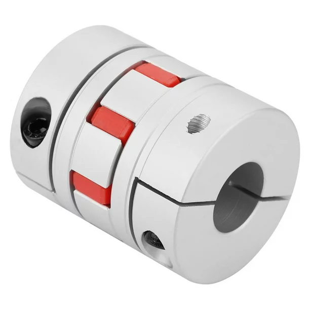
1. The main body is made of high strength aluminum alloy
2. Zero backlash, suitable for forward and reverse rotation
3.Colloid is made of polyurethane, which has good wear resistance
4.Oil resistance and electrical insulation, the middle elasticbody can absorb vibration
5. Compensate radial, angular and axial deviations
6. Removable design for easy installation
7. Tightening method of positioning screw
Suitable for a wide range of devices
CNC lathes Optical inspection equipment
Module slider Servo motor
Company Profile
Certifications
Packaging & Shipping
All products will be well packed with standard export wooden case or
cartons.
Shafts packed with paper tube or plastic bag;
Linear guideways or lead screwswrapped with film or plastic bag;
Guarantee well protected against dampness,moisture, rust and shock.
Our Advantages
FAQ
Q1: Do you have a catalogue? Can you send me the catalogue to have a check of all your products?
A: Yes , We have product catalogue.Please contact us on line or send an Email to sending the catalogue.
Q2: I can’t find the product on your catalogue, can you make this product for me?
A: Our catalogue shows most of our products,but not all.So just let us know what product do you need.
Q3 : Can you make customized products and customized packing?
A: Yes.We made a lot of customized products for our customer before.And we have many moulds for our customers already.About customized packing,we can put your Logo or other info on the packing.There is no problem.Just have to point out that ,it will cause some additional cost.
Q4: Can you provide samples ? Are the samples free ?
A: Yes,we can provide samples.Normally,we provide 1-2pcs free samples for test or quality checking.But you have to pay for the shipping cos.If you need many items, or need more qty for each item,we will charge for the samples.
Any requirements or question,Welcome to “Send” us an e-mail Now!
It’s our great honor to do services for you! You also can get the FREE SAMPLES soon.
What materials are typically used in manufacturing spider couplings and why?
Spider couplings are constructed using a combination of materials to achieve durability, flexibility, and efficient torque transmission. The choice of materials depends on factors such as application requirements, environmental conditions, and the desired balance between strength and flexibility. Common materials used in manufacturing spider couplings include:
- Aluminum: Aluminum is lightweight and corrosion-resistant, making it suitable for applications where weight reduction is important. It offers good mechanical properties and can be used in various industries.
- Steel: Steel provides excellent strength and durability. It’s often used in heavy-duty applications where high torque transmission is required. Surface treatments can enhance corrosion resistance.
- Stainless Steel: Stainless steel offers corrosion resistance in aggressive environments. It’s commonly used in industries such as food processing, pharmaceuticals, and chemical processing.
- Cast Iron: Cast iron is known for its high compressive strength and wear resistance. It’s suitable for applications requiring robust construction and can handle high torque loads.
- Plastic/Polymer: Certain polymers and plastics, such as polyurethane or nylon, are used for the elastomeric spider element. These materials provide flexibility, vibration dampening, and misalignment compensation.
The choice of materials depends on the specific requirements of the application. For example, aluminum or stainless steel may be chosen for industries requiring corrosion resistance, while steel or cast iron may be selected for heavy-duty applications. The elastomeric spider is typically made from a durable polymer to ensure flexibility and effective torque transmission while accommodating misalignment. Overall, selecting the right materials ensures that spider couplings can withstand the demands of the intended application and provide reliable performance over their lifespan.
Are there any recent advancements or innovations in spider coupling technology?
Yes, there have been several recent advancements and innovations in spider coupling technology aimed at enhancing their performance, durability, and versatility. Some of the notable advancements include:
- Advanced Materials: Manufacturers are using new elastomeric materials that offer improved resistance to wear, temperature fluctuations, and chemicals. These materials extend the lifespan of spider couplings and broaden their range of applications.
- Enhanced Designs: Innovative design improvements are being made to optimize torque transmission, misalignment compensation, and vibration dampening. These designs aim to provide better coupling performance in various operating conditions.
- Customization: Some manufacturers offer customizable spider couplings to match specific application requirements. This includes tailoring the coupling’s stiffness, torque capacity, and damping characteristics to suit different machinery and industries.
- Smart Couplings: Integration of sensors and monitoring technology into spider couplings allows real-time data collection on factors such as temperature, vibration, and load distribution. This data helps in predictive maintenance and optimizing equipment performance.
- Composite Couplings: Composite materials are being utilized in spider couplings to provide a balance between lightweight design, high strength, and corrosion resistance. These couplings find applications in industries where weight reduction and durability are critical.
- Energy Efficiency: Some spider couplings are designed with energy efficiency in mind, aiming to reduce power losses due to damping while maintaining reliable torque transmission.
These advancements demonstrate the ongoing efforts to enhance spider coupling technology, making them more adaptable to modern machinery requirements. As technology continues to evolve, spider couplings are becoming increasingly sophisticated and capable of meeting the challenges posed by various industries and applications.
Can you explain the role of the elastomeric spider in a spider coupling’s function?
The elastomeric spider plays a critical role in the function of a spider coupling by providing flexibility, misalignment compensation, and vibration dampening. It is the central component that connects the two hubs of the coupling and transmits torque between the shafts. The elastomeric spider is typically made from a durable and resilient elastomer material, such as rubber or polyurethane. Here’s how the elastomeric spider contributes to the spider coupling’s operation:
- Flexibility: The elastomeric material of the spider allows it to flex and deform as torque is transmitted between the shafts. This flexibility accommodates misalignment between the shafts, including angular, radial, and axial misalignment.
- Misalignment Compensation: The spider coupling’s design incorporates the elastomeric spider’s ability to stretch and compress. This allows it to absorb and compensate for minor misalignments that can occur due to manufacturing tolerances, thermal expansion, or external forces.
- Vibration Dampening: The elastomeric material of the spider acts as a cushion, absorbing and dampening vibrations that may be generated during operation. This reduces the transmission of vibrations from one shaft to another and contributes to smoother machinery performance.
- Torque Transmission: As the shafts rotate and torque is applied to one hub of the coupling, the elastomeric spider deforms to transmit the torque to the other hub and, subsequently, to the second shaft. The spider’s ability to deform under load ensures efficient power transmission.
- Resilience: Elastomeric spiders are designed to withstand repeated cycles of deformation and load. Their resilience allows them to maintain their original shape and performance over time, contributing to the longevity of the coupling.
- Reduced Maintenance: The presence of the elastomeric spider reduces the need for constant alignment adjustments and maintenance, as it compensates for misalignments and dampens vibrations that can cause wear and tear.
Overall, the elastomeric spider’s ability to provide flexibility, misalignment compensation, vibration dampening, and efficient torque transmission makes it a crucial component in spider couplings, enhancing their performance and reliability in various industrial applications.
editor by CX 2023-08-09
China wholesaler L100 Flexible Jaw Coupling ac coupling
Product Description
L100 flexible jaw coupling
AVAILABLE SIZES: 35, 50, 70, 75, 90, 95, 99, 100, 110, 150, 190, 225
L100 Lovejoy L coupling ,L COUPLING ,L TYPE FLEXIBLE JAW COUPLING
1. Material :Cast iron GG25
2. Good stability
3. Easy to maintain
4.OEM
L coupling have below advantage :
1. It is easy to maintain ,no need the tool can install
2. Can undertake high torque
3. Have the good buffer .
Features:
Economical and practical using
Easy pulling out
Simple construction and light weight
NBR rubber with excellent resistance to oil and drugs
Minimum space
No lubrication
L coupling parameters and data :
| Coupling type | Rated torque | HP-100PRM | |||||||
| In-Lbs. | Horsepower Capacity at Varying Speed(RPM) | Max Bore | |||||||
| Rubber | Hytrel | Rubber | Hytrel | 300 | 1200 | 1800 | 3600 | ||
| L-035 | 3.5 | 0.0056 | 0.017 | 0.067 | 0.1 | 0.2 | 3/8 | ||
| L-050 | 25.2 | 0.04 | 0.12 | 0.48 | 0.72 | 1.44 | 5/8 | ||
| L-070 | 37.8 | 0.06 | 0.18 | 0.72 | 1.08 | 2.16 | 3/4 | ||
| L-075 | 75.6 | 0.12 | 0.36 | 1.44 | 2.16 | 4.32 | 7/8 | ||
| L-090 | 126 | 0.2 | 0.6 | 2.4 | 3.6 | 7.2 | 7/8 | ||
| L-095 | 176 | 0.28 | 0.84 | 3.36 | 5.04 | 10.8 | 1-1/8 | ||
| L-099 | 265 | 0.42 | 1.26 | 5.04 | 7.56 | 15.1 | 1-3/16 | ||
| L-100 | 278 | 0.6 | 1.8 | 7.2 | 10.8 | 21.6 | 1-3/8 | ||
| L-110 | 693 | 2079 | 1.1 | 3.3 | 3.3 | 13.2 | 19.8 | 39.6 | 1-5/8 |
| L-150 | 1071 | 3213 | 1.7 | 5.1 | 5.1 | 20.4 | 30.6 | 61.2 | 1-7/8 |
|
Shipping Cost:
Estimated freight per unit. |
To be negotiated|
|
|---|
| Material: | Aluminium,Cast Iron |
|---|---|
| Surface Finishing: | Blacken |
| Certification: | ISO |
| Customization: |
Available
| Customized Request |
|---|

Programming With Couplings
A coupling is a mechanical device that connects two shafts together and transmits power. Its purpose is to join rotating equipment and allows some degree of end-movement or misalignment. There are many different types of couplings. It’s important to choose the right one for your application.
Mechanical connection between two shafts
There are many ways to achieve mechanical connection between two shafts, including the use of a coupling. One common type is the beam coupling, which is also known as a helical coupling. It is used for transmission of torque between two shafts. This type of connection accommodates axial, parallel and angular misalignments.
The hubs and shafts of a worm gear are connected together by a coupling. This mechanical connection allows one shaft to turn another without causing a mechanical failure. This type of coupling is made from sliding or rubbing parts to transfer torque. However, the coupling is not designed to withstand jerks, so it isn’t suitable for high-speed applications.
The use of a coupling is common in machinery and equipment. It helps transmit power from one drive shaft to the other, while adding mechanical flexibility. It is also useful for reducing the impact and vibration caused by misalignment. It also protects the drive shaft components from wear and tear.
A double-hook coupling can be used to provide a uniform angular velocity at the driven shaft. Another example is a double-jointed coupling. A double-jointed coupling can be used to connect shafts that are not directly intersecting. The double-jointed yoke can be used for the same purpose.
A shaft coupling is a device that maintains a strong mechanical connection between two shafts. It transfers motion from one shaft to another, at all loads and misalignments. Unlike a conventional linkage, a shaft coupling isn’t designed to allow relative motion between the two shafts. Couplings often serve several purposes in a machine, but their primary use is torque and power transmission.
Functions that control the flow of another function
One of the simplest programming constructs is a function that controls the flow of another function. A function can take an argument and return a different value, but it must be ready to return before it can pass that value to another function. To do this, you can use the goto statement and the if statement. Another way to control flow is to use a conditional statement.
Criteria for selecting a coupling
There are several important factors to consider when choosing the right coupling. One of the most important factors is coupling stiffness, which depends on the material used and the shape. The stiffness of a coupling determines its ability to resist elastic deformation. A stiff coupling is desirable for certain types of applications, but it’s undesirable for others. Stiffness can reduce the performance of a system if there’s too much inertia. To avoid this, ensure that the coupling you choose is within the recommended limits.
The size of a coupling is also important. Different coupling types can accommodate different shaft sizes and shapes. Some couplings have special features, such as braking and shear pin protection. When choosing a coupling, you should also consider the type of driven equipment. If you need to connect a high-torque motor, for example, you’ll want to choose a gear coupling. Likewise, a high-speed machine may require a disc coupling.
Another factor to consider when selecting a coupling is the torque rating. Despite its importance, it’s often underestimated. The torque rating is defined as the torque of the coupling divided by its OD. In some cases, torque may fluctuate during a cycle, requiring a coupling with a higher torque rating.
Torsionally flexible couplings are also important to consider. Their design should be able to withstand the torque required during operation, as well as the required speed. The coupling should also have a high degree of torsional stiffness, as well as damping. Furthermore, a damping coupling can reduce the energy wasted through vibration.
The sizing of a coupling is also determined by the torque. Many engineers use torque to select the correct coupling size, but they also take into consideration torsional flexibility and torsional stiffness. For example, a shaft may be able to handle large torque without damaging the coupling, while a disk may be unable to handle large amounts of torque.
Besides torque, another important consideration in coupling selection is the cost. While a coupling may be cheaper, it may be less reliable or easier to maintain. Couplings that are difficult to service may not last as long. They may also require frequent maintenance. If that’s the case, consider purchasing a coupling with a low service factor.
There are many different types of couplings. Some require additional lubrication throughout their lifetime, while others are 100% lubrication-free. An example of a 100% lubrication-free coupling is the RBI flexible coupling from CZPT. This type of coupling can significantly reduce your total cost of ownership.
In addition to the above-mentioned benefits, elastomeric couplings are low-cost and need little maintenance. While they are often cheaper than metallic couplings, they also have excellent shock absorption and vibration dampening properties. However, they are susceptible to high temperatures. Also, they are difficult to balance as an assembly, and have limited overload torque capacity.
editor by CX 2023-06-02
China Custom Jaw Coupling Transmission Parts Rubber Spider Coupler Good Price Small Dimensions Transmit Torque Stainless Steel Anti-Rusty Industrial Couplings Jaw Coupling define coupling
Product Description
Jaw Coupling Transmission Parts Rubber Spider Coupler Good Price Small Dimensions Transmit Torque Stainless Steel Anti-Rusty Industrial Couplings Jaw Coupling
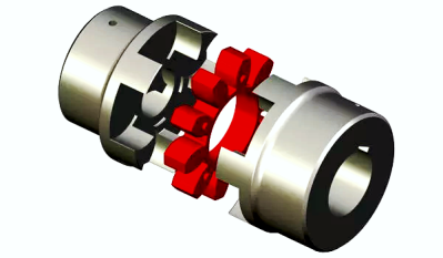
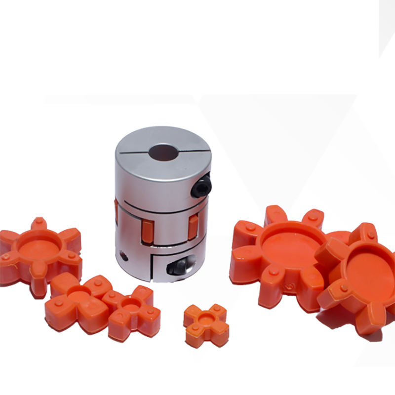
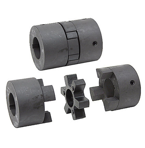
A jaw coupling is a type of general purpose power transmission coupling that also can be used in motion control (servo) applications. It is designed to transmit torque (by connecting 2 shafts) while damping system vibrations and accommodating misalignment, which protects other components from damage. Jaw couplings are composed of 3 parts: 2 metallic hubs and an elastomer insert called an element, but commonly referred to as a “spider”. The 3 parts press fit together with a jaw from each hub fitted alternately with the lobes of the spider. Jaw coupling torque is transmitted through the elastomer lobes in compression.
| Standard Or Nonstandard: | Standard |
|---|---|
| Shaft Hole: | 8-24 |
| Torque: | >80N.M |
| Bore Diameter: | 19mm |
| Speed: | 4000r/M |
| Structure: | Flexible |
| Samples: |
US$ 9999/Piece
1 Piece(Min.Order) | |
|---|

Types of Coupling
A coupling is a device used to join two shafts together and transmit power. Its primary function is to join rotating equipment and allows for some end movement and misalignment. This article discusses different types of coupling, including Magnetic coupling and Shaft coupling. This article also includes information on Overload safety mechanical coupling.
Flexible beam coupling
Flexible beam couplings are universal joints that can deal with shafts that are offset or at an angle. They consist of a tube with couplings at both ends and a thin, flexible helix in the middle. This makes them suitable for use in a variety of applications, from motion control in robotics to attaching encoders to shafts.
These couplings are made of one-piece materials and are often made of stainless steel or aluminium alloy. However, they can also be made of acetal or titanium. While titanium and acetal are less common materials, they are still suitable for high-torque applications. For more information about beam couplings, contact CZPT Components.
Flexible beam couplings come in a variety of types and sizes. W series couplings are good for general purpose applications and are relatively economical. Stainless steel versions have increased torque capacity and torsional stiffness. Flexible beam couplings made of aluminum are ideal for servo and reverse motion. They are also available with metric dimensions.
Flexible beam couplings are made of aluminum alloy or stainless steel. Their patented slot pattern provides low bearing load and high torsional rigidity. They have a long operational life. They also require zero maintenance and can handle angular offset. Their advantages outweigh the disadvantages of traditional beam couplings.
Magnetic coupling
Magnetic coupling transfers torque from one shaft to another using a magnetic field. These couplings can be used on various types of machinery. These types of transmissions are very useful in many situations, especially when you need to move large amounts of weight. The magnetic field is also very effective at reducing friction between the two shafts, which can be extremely helpful if you’re moving heavy items or machinery.
Different magnetic couplings can transmit forces either linearly or rotated. Different magnetic couplings have different topologies and can be made to transmit force in various geometric configurations. Some of these types of couplings are based on different types of materials. For example, a ceramic magnetic material can be used for applications requiring high temperature resistance.
Hybrid couplings are also available. They have a hybrid design, which allows them to operate in either an asynchronous or synchronous mode. Hysterloy is an alloy that is easily magnetized and is used in synchronous couplings. A synchronous magnetic coupling produces a coupled magnetic circuit.
Magnetic coupling is a key factor in many physical processes. In a crystal, molecules exhibit different magnetic properties, depending on their atomic configuration. Consequently, different configurations produce different amounts of magnetic coupling. The type of magnetic coupling a molecule exhibits depends on the exchange parameter Kij. This exchange parameter is calculated by using quantum chemical methods.
Magnetic couplings are most commonly used in fluid transfer pump applications, where the drive shaft is hermetically separated from the fluid. Magnetic couplings also help prevent the transmission of vibration and axial or radial loads through the drive shaft. Moreover, they don’t require external power sources, since they use permanent magnets.
Shaft coupling
A shaft coupling is a mechanical device that connects two shafts. The coupling is designed to transmit full power from one shaft to the other, while keeping the shafts in perfect alignment. It should also reduce transmission of shock loads. Ideally, the coupling should be easy to connect and maintain alignment. It should also be free of projecting parts.
The shaft couplings that are used in machines are typically made of two types: universal coupling and CZPT coupling. CZPT couplings are designed to correct for lateral misalignment and are composed of two flanges with tongues and slots. They are usually fitted with pins. The T1 tongue is fitted into flange A, while the T2 tongue fits into flange B.
Another type of shaft coupling is known as a “sliced” coupling. This type of coupling compensates for inevitable shaft misalignments and provides high torque. Machined slits in the coupling’s outer shell help it achieve high torsional stiffness and excellent flexibility. The design allows for varying engagement angles, making it ideal for many different applications.
A shaft coupling is an important component of any machine. Proper alignment of the two shafts is vital to avoid machine breakdowns. If the shafts are misaligned, extra force can be placed on other parts of the machine, causing vibration, noise, and damage to the components. A good coupling should be easy to connect and should ensure precise alignment of the shaft. Ideally, it should also have no projecting parts.
Shaft couplings are designed to tolerate a certain amount of backlash, but it must be within a system’s threshold. Any angular movement of the shaft beyond this angle is considered excessive backlash. Excessive backlash results in excessive wear, stress, and breakage, and may also cause inaccurate alignment readings. It is therefore imperative to reduce backlash before the shaft alignment process.
Overload safety mechanical coupling
Overload safety mechanical couplings are devices that automatically disengage when the torque applied to them exceeds a specified limit. They are an efficient way to protect machinery and reduce the downtime associated with repairing damaged machinery. The advantage of overload couplings is their fast reaction time and ease of installation.
Overload safety mechanical couplings can be used in a wide range of applications. Their automatic coupling mechanisms can be used on any face or edge. In addition, they can be genderless, incorporating both male and female coupling features into a single mechanism. This means that they are both safe and gender-neutral.
Overload safety couplings protect rotating power transmission components from overloads. Overload protection devices are installed on electric motors to cut off power if the current exceeds a certain limit. Likewise, fluid couplings in conveyors are equipped with melting plug elements that allow the fluid to escape when the system becomes too hot. Mechanical force transmission devices, such as shear bolts, are designed with overload protection in mind.
A common design of an overload safety mechanical coupling consists of two or more arms and hubs separated by a plastic spider. Each coupling body has a set torque threshold. Exceeding this threshold may damage the spider or damage the jaws. In addition, the spider tends to dampen vibration and absorb axial extension. This coupling style is nearly backlash free, electrically isolating, and can tolerate very little parallel misalignment.
A mechanical coupling may also be a universal joint or jaw-clutch coupling. Its basic function is to connect the driver and driven shafts, and limits torque transfer. These devices are typically used in heavy-duty industries, such as steel plants and rolling mills. They also work well with industrial conveyor systems.
CZPT Pulley
The CZPT Pulley coupling family offers a comprehensive range of couplings for motors of all types. Not only does this range include standard motor couplings, but also servo couplings, which require ultra-precise control. CZPT Pulley couplings are also suitable for engine applications where high shocks and vibrations are encountered.
CZPT Pulley couplings have a “sliced” body structure, which allows for excellent torsional stiffness and strength. They are corrosion-resistant and can withstand high rotational speeds. The couplings’ design also ensures accurate shaft rotation while limiting shaft misalignment.
CZPT Pulley has introduced the CPU Pin Type couplings, which are effective at damping vibration and maintain zero backlash. They are also made from aluminum and are capable of absorbing heat. They come with recessed tightening screws. They can handle speeds up to 4,000 RPM, and are RoHS-compliant.
editor by CX 2023-05-31
China wholesaler CZPT Lm Type Basic High Efficiency Flexible Aluminum Star Jaw Coupling coupling and types of coupling
Product Description
LM Basic Type Plum Elastic Coupling(GB/T 5272-2002)
♦Description
Plum elastic coupling has the characteristics of vibration reduction, buffering, small radial size, no lubrication and easy maintenance. Suitable for starting frequency, positive and negative rotation, medium and low speed, medium and small power transmission.Not suitable for heavy loads and frequent replacement of elastic elements.
The structure of plum elastic coupling is simple. But when the elastic element is replaced, the half coupling shall be moved axially.LMS type is easy to replace the elastic element without having to move the half coupling.
♦Detailed Pictures
♦Basic Parameter and Main Dimension
| Type | Norminal torque(Tn/N·m) | Speed(Np) | Shaft hole diameter (d1,d2,dz) |
Length of shaft hole | LO | D | D1 | Type of elastic parts | Mass | Rotary inertia | ||||||||||||||
| Hardness of elastic parts | LM | LMD,LMS | Y type | J1,Z type | L (recommend) |
LM | LMD | LMS | LMD,LMS | LM | LMD | LMS | LM | LMD | LMS | |||||||||
| a/HA | b/HD | L | ||||||||||||||||||||||
| 80+5 | 60+5 | r·min-1 | Mm | kg | kg·m2 | |||||||||||||||||||
| LM1 LMD1 LMS1 |
25 | 45 | 15300 | 8500 | 12,14 | 32 | 27 | 35 | 86 | 92 | 98 | 50 | 90 | MT1-a -b | 0.66 | 1.21 | 1.33 | 0.0002 | 0.0008 | 0.0013 | ||||
| 16,18,19 | 42 | 30 | ||||||||||||||||||||||
| 20,22,24 | 52 | 38 | ||||||||||||||||||||||
| 25 | 62 | 44 | ||||||||||||||||||||||
| LM2 LMD2 LMS2 |
50 | 100 | 1200 | 7600 | 16,18,19 | 42 | 30 | 38 | 95 | 101.5 | 108 | 60 | 100 | MT2-a -b | 0.93 | 1.65 | 1.74 | 0.0004 | 0.0014 | 0.0571 | ||||
| 20,22,24 | 52 | 38 | ||||||||||||||||||||||
| 25,28 | 62 | 44 | ||||||||||||||||||||||
| 30 | 82 | 60 | ||||||||||||||||||||||
| LM3 LMD3 LMS3 |
100 | 200 | 10900 |
6900 | 20,22,24 | 52 | 38 | 40 | 103 | 110 | 117 | 70 | 110 | MT3-a -b | 1.41 | 2.36 | 2.33 | 0.0009 | 0.0571 | 0.0034 | ||||
| 25,28 | 62 | 44 | ||||||||||||||||||||||
| 30,32 | 82 | 60 | ||||||||||||||||||||||
| LM4 LMD4 LMS4 |
140 | 280 | 9000 |
6200 | 22,24 | 52 | 38 | 45 | 114 | 122 | 130 | 85 | 125 | MT4-a -b | 2.18 | 3.56 | 3.38 | 0.002 | 0.005 | 0.0064 | ||||
| 25,28 | 62 | 44 | ||||||||||||||||||||||
| 30,32,35,38 | 82 | 60 | ||||||||||||||||||||||
| 40 | 112 | 84 | ||||||||||||||||||||||
| LM5 LMD5 LMS5 |
350 | 400 | 7300 |
5000 | 25,28 | 62 | 44 | 50 | 127 | 138.5 | 150 | 105 | 150 | MT5-a -b | 3.60 | 6.36 | 6.07 | 0.005 | 0.0135 | 0.0175 | ||||
| 30,32,35,38 | 82 | 60 | ||||||||||||||||||||||
| 40,42,45 | 112 | 84 | ||||||||||||||||||||||
| LM6 LMD6 LMS6 |
400 | 710 | 6100 |
4100 | 30,32,35,38 | 82 | 60 | 55 | 143 | 155 | 167 | 185 | 185 | MT6-a -b | 6.07 | 10.77 | 10.47 | 0.0114 | 0.0329 | 0.0444 | ||||
| 40,42,45,48 | 112 | 84 | ||||||||||||||||||||||
| LM7 LMD7 LMS7 |
630 | 1120 | 5300 | 3700 | 35*,38* | 82 | 60 | 60 | 159 | 172 | 185 | 205 | 205 | MT7-a -b | 9.09 | 15.30 | 14.22 | 0.5712 | 0.0581 | 0.571 | ||||
| 40*,42*,45,48,50,55 | 112 | 84 | ||||||||||||||||||||||
| LM8 LMD8 LMS8 |
1120 | 2240 | 4500 | 3100 | 45*,48*,50,55,56 | 112 | 84 | 70 | 181 | 195 | 209 | 170 | 240 | MT8-a -b | 13.56 | 22.72 | 21.16 | 0. 0571 | 0.1175 | 0.1493 | ||||
| 60,63,65 | 142 | 107 | ||||||||||||||||||||||
| LM9 LMD9 LMS9 |
1800 | 3550 | 3800 | 2800 | 50*,55*,56* | 112 | 84 | 80 | 208 | 224 | 240 | 200 | 270 | MT9-a -b | 21.40 | 34.44 | 30.70 | 0.1041 | 0.2333 | 0.2767 | ||||
| 60,63,65,70,71,75 | 142 | 107 | ||||||||||||||||||||||
| 80 | 172 | 132 | ||||||||||||||||||||||
| LM10 LMD10 LMS10 |
2800 | 5600 | 3300 | 2500 | 60*,63*,65*,70,71,75 | 142 | 107 | 90 | 230 | 248 | 268 | 230 | 305 | MT10-a -b | 32.03 | 51.36 | 44.55 | 0.2105 | 0.4594 | 0.5262 | ||||
| 80,85,90,95 | 172 | 132 | ||||||||||||||||||||||
| 100 | 212 | 167 | ||||||||||||||||||||||
| LM11 LMD11 LMS11 |
4500 | 9000 | 2900 | 2200 | 71*,71*,75* | 142 | 107 | 100 | 260 | 284 | 308 | 260 | 350 | MT11-a -b | 49.52 | 81.30 | 70.72 | 0.4338 | 0.9777 | 1.1362 | ||||
| 80*,85*,90,95 | 172 | 132 | ||||||||||||||||||||||
| 100,110,120 | 212 | 167 | ||||||||||||||||||||||
| LM12 LMD12 LMS12 |
6300 | 12500 | 2500 | 1900 | 80*,85*,90*95 | 172 | 132 | 115 | 297 | 321 | 345 | 300 | 400 | MT12-a -b | 73.45 | 115.53 | 99.54 | 0.8205 | 1.751 | 1.9998 | ||||
| 100,110,120,125 | 212 | 167 | ||||||||||||||||||||||
| 130,140,150 | 252 | 202 | ||||||||||||||||||||||
| LM13 LMD13 LMS13 |
11200 | 2000 | 2100 | 1600 | 90*,95* | 172 | 132 | 125 | 323 | 348 | 373 | 360 | 460 | MT13-a -b | 103.86 | 161.79 | 137.53 | 1.6718 | 3.667 | 3.6719 | ||||
| 100*,110*,120*,125* | 212 | 167 | ||||||||||||||||||||||
| 130,140,150 | 252 | 202 | ||||||||||||||||||||||
| LM14 LMD14 LMS14 |
12500 | 25000 | 1900 | 1500 | 100*,110*,120*,125* | 212 | 167 | 135 | 333 | 358 | 383 | 400 | 500 | MT14-a -b | 127.59 | 196.32 | 165.25 | 2.499 | 4.8669 | 5.1581 | ||||
| 130*,140*,150 | 252 | 202 | ||||||||||||||||||||||
| 160 | 302 | 242 | ||||||||||||||||||||||
NOTE:
1. Mass and rotary inertia are the approximation calculated according to the recommended minimum axial hole.
2. Diameter of shaft hole with* can be used for Z type shaft hole.
3. a.b is the code for 2 different materials and hardness of elastic parts.
♦Other Products List
| Transmission Machinery Parts Name |
Model |
| Universal Coupling | WS,WSD,WSP |
| Cardan Shaft | SWC,SWP,SWZ |
| Tooth Coupling | CL,CLZ,GCLD,GIICL, GICL,NGCL,GGCL,GCLK |
| Disc Coupling | JMI,JMIJ,JMII,JMIIJ |
| High Flexible Coupling | LM |
| Chain Coupling | GL |
| Jaw Coupling | LT |
| Grid Coupling | JS |
♦Our Company
HangZhou CZPT Machinery Manufacturing Co., Ltd. is a high-tech enterprise specializing in the design and manufacture of various types of coupling. There are 86 employees in our company, including 2 senior engineers and no fewer than 20 mechanical design and manufacture, heat treatment, welding, and other professionals.
Advanced and reasonable process, complete detection means. Our company actively introduces foreign advanced technology and equipment, on the basis of the condition, we make full use of the advantage and do more research and innovation. Strict to high quality and operate strictly in accordance with the ISO9000 quality certification system standard mode.
Our company supplies different kinds of products. High quality and reasonable price. We stick to the principle of “quality first, service first, continuous improvement and innovation to meet the customers” for the management and “zero defect, zero complaints” as the quality objective.
♦Our Services
1. Design Services
Our design team has experience in Cardan shafts relating to product design and development. If you have any needs for your new product or wish to make further improvements, we are here to offer our support.
2. Product Services
Raw materials → Cutting → Forging →Rough machining →Shot blasting →Heat treatment →Testing →Fashioning →Cleaning→ Assembly→ Packing→ Shipping
3. Samples Procedure
We could develop the sample according to your requirement and amend the sample constantly to meet your need.
4. Research & Development
We usually research the new needs of the market and develop the new model when there is new cars in the market.
5. Quality Control
Every step should be a special test by Professional Staff according to the standard of ISO9001 and TS16949.
♦FAQ
Q 1: Are you a trading company or a manufacturer?
A: We are a professional manufacturer specializing in manufacturing various series of couplings.
Q 2: Can you do OEM?
Yes, we can. We can do OEM & ODM for all the customers with customized artworks in PDF or AI format.
Q 3: How long is your delivery time?
Generally, it is 20-30 days if the goods are not in stock. It is according to quantity.
Q 4: Do you provide samples? Is it free or extra?
Yes, we could offer the sample but not for free. Actually, we have a very good price principle, when you make the bulk order the cost of the sample will be deducted.
Q 5: How long is your warranty?
A: Our Warranty is 12 months under normal circumstances.
Q 6: What is the MOQ?
A: Usually our MOQ is 1 pcs.
Q 7: Do you have inspection procedures for coupling?
A: 100% self-inspection before packing.
Q 8: Can I have a visit to your factory before the order?
A: Sure, welcome to visit our factory.
Q 9: What’s your payment?
A: T/T.
♦Contact Us
Web: huadingcoupling
Add: No.11 HangZhou Road,Chengnan park,HangZhou City,ZheJiang Province,China
| Standard Or Nonstandard: | Standard |
|---|---|
| Shaft Hole: | as Your Requirement |
| Torque: | as Your Requirement |
| Bore Diameter: | as Your Requirement |
| Speed: | as Your Requirement |
| Structure: | Flexible |
| Samples: |
US$ 500/Piece
1 Piece(Min.Order) | |
|---|
| Customization: |
Available
| Customized Request |
|---|

What Is a Coupling?
A coupling is a device that connects two shafts together. It transmits power from one to the other and is used to join rotating equipment. It can also allow for some degree of misalignment and end movement. It is used in mechanical engineering and manufacturing. To learn more about couplings, read this article.
Mechanical connection between two objectsThe present invention relates to a method and assembly for forming a mechanical connection between two objects. The methods of this invention are suitable for connecting both solid and hollow objects. For example, the method can be used to make mechanical connections between two cylinders. This method is particularly useful for connecting two cylinders that are positioned near each other.
Absorbs vibration
A coupling insert is a part of a vehicle’s drivetrain that absorbs vibrations. These inserts are designed to prevent couplings from moving out of phase. However, the coupling inserts themselves can wear out and need to be replaced. Universal joints are an alternative if the coupling is out of phase by more than one degree. In addition, internal bearings in the coupling need to be lubricated and replaced when they begin to show signs of wear.
Another embodiment of the invention includes a flexible coupling 25 that includes rearwardly-extending lugs that extend toward the coupling member 23. These lugs interdigitate with corresponding lugs on the coupling member 23. They are spaced circumferentially. A first elastic member 28 is interposed between lugs 26 and 27, and is adapted to yield in a counterclockwise direction. As a result, it absorbs torsional vibrations.
Blocks heat transfer
Thermal coupling occurs when a solid block is thermally coupled to the air or fluid passing through it. The amount of heat transferred through a solid block depends on the heat transfer coefficients of the materials. This paper presents a numerical model to understand how heat transfers through different block materials. This work also describes the thermal resistance network for a one-dimensional block.
In some cases, thermal coupling increases the heat transfer mechanism. As illustrated in FIG. 1D, a heatpipe coupler 112 couples two heatpipes 110-1 and 110-2. This configuration allows the pipes to be coupled to the heat source and to the condenser. In addition, the heat pipe couplers may have bellows at the ends to help facilitate linear motion.
Thermal coupling is achieved by ensuring that at least one block is made of a material with a lower thermal expansion coefficient than the annulus. Ideally, the block’s mean thermal expansion coefficient is at least twenty percent lower than the annulus’s mean thermal expansion coefficient. This ensures that the thermal coupling between the two parts is as efficient as possible.
Another type of thermal coupling is achieved by using flexible elements. These are often washers or springs. These components allow the blocks to maintain physical contact with the post 55, which means that the heat transfer is more efficient even at higher temperatures. The flexibility of these elements also makes it possible to choose an element that will not impede assembly.
Protects rotating equipment
A reliable, long-lasting coupling system can reduce the risk of damage to rotating equipment. Designed to protect against torque overload and wear, Voith torque-limiting couplings provide outstanding safety and reliability. As a result, they can deliver maximum performance and minimize equipment downtime. In addition to their long-term benefits, these solutions are ideal for applications where safety and reliability are of paramount importance.
A good coupling provides many advantages, including the ability to transmit power, compensate for axial movement, and absorb shock. It is essential to choose the proper coupling for your application based on the basic conditions of your rotating equipment. For example, if you have two shafts with parallel rotation axes, you should choose a parallel coupling. Otherwise, you should use an angular coupling.
Torque-limiting couplings can also provide protection for rotating equipment by disengaging at a specific torque level. This protects the drive shaft from undergoing catastrophic failure. Torque limiters are particularly helpful for high-value equipment. By preventing catastrophic failure, you can avoid expensive repairs and minimize equipment downtime.
Coupling guards are easy to install and provide effective protection for rotating equipment. These covers are made of sheet metal bent to fit over the shaft. They are durable and easy to remove when necessary. This type of guard can prevent employees from catching their hands, tools, or loose clothing on motor coupling components.
editor by CX 2023-05-08
China Curved Jaw Sbt Type Polyurethane Coupling Spider cohesion and coupling
Solution Description
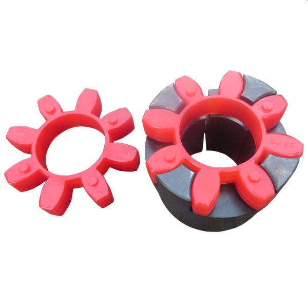
Curved Jaw SBT Type Polyurethane Coupling Spider Rubber Cushion Pad
Specification:
| Name | SBT Coupling Rubber Factor Spider |
| Substance | Silicone, EPDM, NR, NBR, FKM, SBR, HNBR, IIR, CR FFKM etc silicon,fluorine,NBR,FPM,EPDM,SILCONE ACM,HNBR |
| Dimensions | According to the drawing or sample |
| Shade | In accordance to your prerequisite (Panton coloration card) |
| Software | Elements are utilized on cars, printing devices, foodstuff processing devices, textile equipment, electronic equipment, and so on. |
| Inspection instruments | Exceptional chemical and actual physical home, outstanding oil- resistance, high temperature stability, and many others. |
| Deal | Inner plastic bag/outside carton/wood pallets/ or any other specific bundle as for every customer’s requirements |
| Final inspection | We are going to make a last QC a hundred% inspection to make confident a excellent quality before supply |
Characteristics:
- Extended executing life
- Warmth resistance
- Crack proof
Rewards:
- Excellent physical houses.
- Simple set up.
- Technical Information
- Running circumstances
- Temperature: forty~+100°C
- Torque: 22.42500NM
- Materials: PU/Rubber/NBR
- Hardness: 9098Shore A customized
- Color: pink,white,environmentally friendly,yellow,black or personalized
| Coupling Type | Serial No | Lobe | Hardness | |
| SBT ELASTIC SPIDER | T-40 | PU Spider | six | SHA93 |
| SBT ELASTIC SPIDER | T-forty five | PU Spider | 6 | SHA93 |
| SBT ELASTIC SPIDER | T-fifty six | PU Spider | 8 | SHA93 |
| SBT ELASTIC SPIDER | T-62 | PU Spider | 6 | SHA93 |
| SBT ELASTIC SPIDER | T-65 | PU Spider | 6 | SHA93 |
| SBT ELASTIC SPIDER | T-75 | PU Spider | six | SHA93 |
| SBT ELASTIC SPIDER | T-seventy nine | PU Spider | six | SHA93 |
| SBT ELASTIC SPIDER | T-90 | PU Spider | six | SHA93 |
| SBT ELASTIC SPIDER | T-ninety four | PU Spider | six | SHA93 |
| SBT ELASTIC SPIDER | T-104 | PU Spider | six | SHA93 |
| SBT ELASTIC SPIDER | T-108 | PU Spider | 6 | SHA93 |
| SBT ELASTIC SPIDER | T-126 | PU Spider | six | SHA93 |
| SBT ELASTIC SPIDER | T-133 | PU Spider | six | SHA93 |
| SBT ELASTIC SPIDER | T-154 | PU Spider | six | SHA93 |
| SBT ELASTIC SPIDER | T-one hundred seventy | PU Spider | six | SHA93 |
| SBT ELASTIC SPIDER | T-one hundred seventy five | PU Spider | 8 | SHA93 |
| SBT ELASTIC SPIDER | T-a hundred and eighty | PU Spider | 6 | SHA93 |
| SBT ELASTIC SPIDER | T-200 | PU Spider | six | SHA93 |
Application
Other associated coupling splider
FAQ
Q: Are you maker or investing company?
A: We are company, engineer experienced abundant encounter over 20 several years.
Q: How to get the fastest quotation?
A: Sending drawing, substance, amount and other rrequirements by email.
Q: How to get quotation without having drawing?
A: Feasible send out sample, images or element descriptions of merchandise to us, we will return you drawing for validate.
Q: I have an idea for a new product, but not sure if it can be manufactured. Can you help?A. Yes! We are always happy to work with potential customers to evaluate the technical feasibility of your idea or design and we can advise on materials, tooling and likely set-up costs.
Q: My custom items have already been developed on CAD. Can you use the drawings?
A. Yes! DWG, DXF, IGES, Solidworks and Rhino files can all be used to generate quotes, models and mould tools – this can save time and money in producing your parts.
Q: Can I test my idea/solution before committing to mould tool manufacture?
A. Yes, we can use CAD drawings to make models for design and functional evaluations.
Q: What type of plastic/rubber content is best for my design/merchandise?
A. Materials selection depends on the application of your design and the environment in which it will function. We will be happy to discuss the alternatives and suggest the best material.
Q: How to get sample?
A: Free of charge sample is obtainable for your high quality analysis, but you need to spend the freight. Relating to customise products, sample and mould purchase will go initial before mass manufacturing.
| Usage: | Industrial |
|---|---|
| Material: | Rubber, NBR, PU |
| OEM/ODM: | Yes |
| Color: | Custom |
| Serial: | T |
| Hardness: | Sha93 |
| Samples: |
US$ 3/Piece
1 Piece(Min.Order) | |
|---|
| Customization: |
Available
| Customized Request |
|---|
Types of Couplings
A coupling is a device that connects two shafts together. It transmits power from one end to another and is used for joining rotating equipment. A coupling is flexible and can accommodate a certain amount of end movement and misalignment. This allows for more flexibility in applications. Various types of couplings are available, and each one serves a specific purpose.
Shaft couplings
There are many types of shaft couplings, and they are used in a wide range of applications. The type you need depends on the torque, speed, and horsepower you need, as well as the size of the shaft and its spatial limitations. You may also need to consider whether the coupling will accommodate misalignment.
Some shaft couplings are flexible, while others are rigid. Flexible couplings can accommodate up to two degrees of misalignment. They are available in different materials, including aluminum, stainless steel, and titanium. They can also be known by different names, depending on the industry. Some couplings can also be used in a single or multiple-shaft application.
The first type of shaft coupling is a rigid coupling, which consists of two parts that fit together tightly around the shafts. These couplings are designed to have more flexibility than sleeved models, and they can be used on fixed shafts as well. The flanged coupling, on the other hand, is designed for heavy loads and is made of two perpendicular flanges. The flanges are large enough to accommodate screws and are generally used with heavy-duty applications.
CZPT shaft couplings are a great choice if you’re looking for a shaft coupling that delivers high performance, durability, and low cost. These metal disc-style couplings provide low backlash and high torsional stiffness. Their high misalignment tolerance reduces reaction loads on connected components, which makes them ideal for high-speed precision applications. Available in single and double-disc models, they have torque ratings of up to 2,200 in-lbs. (250N) and are available in fourteen sizes.
When using shaft couplings, it is important to choose the right type for your application. Backlash can cause a shaft coupling to break or become unusable. In order to prevent this from happening, you should replace worn or loose parts, and ensure that the hub and key are evenly positioned with the shaft. If you’re using a shaft coupling in a motion-control system, it is important to keep the torque level consistent.
Flexible couplings
Flexible couplings are a type of coupling used to connect two shafts. They are made of rubber or plastic and allow for axial movement of the connected equipment. They do not require lubrication and are resistant to fatigue failure. Flexible couplings are useful for a number of applications. A common type of flexible coupling is the gear coupling, which has gear teeth inside its sleeve. Another type of flexible coupling is the metallic membrane coupling. A metallic membrane coupling is flexible due to flexing metallic discs.
One major disadvantage of flexible couplings is their inability to fit certain types of pipe. This is because most couplings need to be stretched to fit the pipe. This problem is often the result of a change in pipe technology. Traditionally, drain and soil pipe is made of ductile iron or cast iron. Today, most pipes are made of PVC, which has a larger outside diameter than either cast or ductile iron. Because of these changes in pipe technology, many coupling manufacturers have not updated their mold sizing.
Flexible couplings can be either metallic, elastomeric, or a combination of the three. While there are some common characteristics of each type, you should always consider the tradeoffs of each type before choosing one. Generally, the most important considerations when selecting a flexible coupling are torque, misalignment, and ease of assembly and maintenance.
Flexible couplings are used in a wide range of industries. They are useful for connecting two pipes to ensure torque transfer. Although the types available are different, these are the most adaptable couplings in the market. They can withstand movement, vibration, and bending without causing any damage to the piping.
Clutch couplings
A clutch coupling connects two rotating shafts by friction. The clutch engages power when the engine is running, disengaging power when the brake is applied. Clutch couplings are used in applications where the speed of a machine is variable or where continuous service is required. The clutch can transmit power, torque, and axial force.
Clutch couplings come in a variety of styles and configurations. Some couplings are flexible, while others are rigid. Flexible couplings are available in a variety of materials, including stainless steel and aluminum. Some couplings also have a non-backlash design, which helps compensate for misalignment.
Clutch couplings may be synchronous or asynchronous. Synchronous couplings engage and disengage automatically when the driven machine exceeds its output speed. These couplings are synchronized by a synchronizing mechanism. When the output speed is exceeded, the synchronizing mechanism initiates the engagement process. The synchronizing mechanism does not engage or disengage when the output speed drops.
High speed clutches are available from a variety of manufacturers. Some manufacturers offer OEM assembly, repair services, and third-party logistics. These manufacturers serve the automotive, chemical, food, and wood industries, as well as the oilfield and material handling industries. Custom clutches can be manufactured for specific applications and can be fitted with additional features, such as precision machined teeth or keyway slots and grooves.
Couplings are available in PCE, C/T, and metric bores. Typically, the size of the input and output shafts will determine which type of coupling is needed. In addition, clutches may be configured for intermediate or high speeds, depending on the required torque.
Clamped couplings
Clamped couplings are commonly used in a variety of industries. They can be used in medical equipment, dental equipment, military equipment, laboratory equipment, and in precision industrial controls. They are available in a wide variety of sizes and keyways. This type of coupling offers a number of advantages, including ease of installation and quick and easy replacement.
A clamp coupling connects two parts by compressing them together. The clamping elements can be formed in a variety of ways, but they all have a gap between their surfaces. This friction squeezes the two parts together, much like pulling two rubber gloves apart. This type of coupling is also useful for joining two hoses or piping units.
Clamped couplings are designed with a single or double clamping shaft. The clamping parts are mounted in two halves and are held together by eight socket head cap screws. They offer high torque capacity and require little installation space. Their high rigidity ensures good positioning accuracy, making them ideal for dynamic drives. In addition, they are wear-free and offer simple radial assembly.
The invention relates to a method and system for clamping pipes to a tank vessel. This invention also relates to a method of loading and unloading tank vessels. The method can be used in oil production platforms and other platforms. A single point mooring method is also used in oil production platforms.
Clamped couplings can also be flexible. They can join two shafts together while allowing a small amount of end movement and misalignment. These couplings may also be used in the assembly of motors and gearboxes.
CZPT’s coupling
CZPT couplings are designed to be flexible, allowing them to accommodate misaligned shafts and transmit torque in either direction. They are made with three discs, two hubs, and a center that are arranged with grooves and fins. These features allow for two degrees of freedom during assembly, and can accommodate misalignment of up to 5% of the shaft diameter.
CZPT couplings have many uses. For example, they can be used to join two parallel coaxial rotating shafts. Their ability to transmit torque at the same rotation mechanism and speed makes them ideal for applications where electrical currents may be a problem. Because the couplings are not made of metal, they are electrically isolated. Designers should test their couplings during the prototype stage to ensure they are working properly.
The CZPT coupling consists of two hubs with one slot on each. An intermediate disk is located between the two hubs. The discs are used to reduce or prevent wear on other machine parts. CZPT couplings are inexpensive and easy to replace. They also have electrical insulation, which makes them easy to repair or replace.
CZPT couplings are a popular choice for stepper motor-driven positioning stages. The plastic center disc offers electrical isolation and absorbs shocks from frequent start/stops. These couplings are available in through-hub and blind-bore styles and can be installed in many applications.
CZPT couplings also allow for small degrees of shaft misalignment. This allows them to function in systems where shaft access is limited. They are easily removed without tools.
editor by CX 2023-04-12
China Zero Backlash Elastomer Insert Elastic Jaw Flexible Shaft Coupling supplier
Item Description
Merchandise Description:
Coupling is employed to website link the 2 distinct companies shaft (driving shaft and driven shaft) to rotate to frequent transmission torque of mechanical areas.The overloaded energy transmission at high velocity, some coupling and buffer, vibration and increase the part of shaft method dynamic performance.Coupling is made up of 2 parts, respectively, and the driving shaft and driven shaft link.
| Brand | SHAC |
| Uncooked substance | Aluminum |
| Inner Diameter | four-60MM |
| Size | twenty five-140MM |
| Design variety | JM1,JM2,JDM,JM-T,JH,TM1/TM2/TM3/TM4,JB,JG,JT |
| Packing | Plastic bag+inner box.According to customer’s request |
| Sample | Free of charge sample and catalogue available |
| Certification | ISO 9001 , ISO 14001 , ISO 14000 |
| Software | CNC machines, healthcare and meals equipment, health and fitness machinery, packaging machinery, printing equipment, and other equipment supporting gear. |
Services:
one,Our Staff:
We have skilled and qualified staff of advertising and revenue representatives to provide our valued clients with the very best merchandise and unsurpassed support.And have specialist engineers crew to evaluation and development the new precision items,and make the OEM custom-made more very easily,skilled QC staff to test the products quaity make certain the merchandise top quality prior to shipping out.
2,Our merchandise:
Quality is the existence .We use only the very best top quality material to ensure the precision of our
Item.All products we bought out are strictly picked and examined by our QC department.
3,Payment:
We accept payment through TT (Financial institution transfer), L/C,Western Union.
four,Shipping and delivery method:
Including DHL, UPS, TNT, FEDEX,EMS, Airfreight and by Sea,as consumer required.
| To Be Negotiated | 1 Piece (Min. Order) |
###
| Standard Or Nonstandard: | Standard |
|---|---|
| Shaft Hole: | Different Size as Requirement |
| Torque: | More Than 10n.M |
| Bore Diameter: | 4mm~60mm,Different Size with Different |
| Speed: | Different Size Maximum Rpm Different as Standard |
| Structure: | Flexible |
###
| Samples: |
US$ 0/Piece
1 Piece(Min.Order) |
|---|
###
| Customization: |
Available
|
|---|
###
| Brand | SHAC |
| Raw material | Aluminum |
| Inner Diameter | 4-60MM |
| Length | 25-140MM |
| Model number | JM1,JM2,JDM,JM-T,JH,TM1/TM2/TM3/TM4,JB,JG,JT |
| Packing | Plastic bag+inner box.According to customer‘s request |
| Sample | Free sample and catalogue available |
| Certification | ISO 9001 , ISO 14001 , ISO 14000 |
| Application | CNC machines, medical and food machinery, fitness machinery, packaging machinery, printing machinery, and other machinery supporting equipment. |
What Is a Coupling?
A coupling is a device used to connect two shafts. It transmits power between them and allows for some misalignment or end movement. There are several types of couplings. The most common ones are gear couplings and planetary couplings. However, there are many others as well.
Transfer of energy
Energy coupling is a process by which two biological reactions are linked by sharing energy. The energy released during one reaction can be used to drive the second. It is a very useful mechanism that synchronizes two biological systems. All cells have two types of reactions, exergonic and endergonic, and they are connected through energy coupling.
This process is important for a number of reasons. The first is that it allows the exchange of electrons and their energy. In a single molecule, this energy transfer involves the exchange of two electrons of different energy and spin. This exchange occurs because of the overlap interaction of two MOs.
Secondly, it is possible to achieve quadratic coupling. This is a phenomenon that occurs in circular membrane resonators when the system is statically deflected. This phenomenon has been gaining a great deal of interest as a mechanism for stronger coupling. If this mechanism is employed in a physical system, energy can be transferred on a nanometer scale.
The magnetic field is another important factor that affects the exchange of energy between semiconductor QWs. A strong magnetic field controls the strength of the coupling and the energy order of the exciton. The magnetic field can also influence the direction of polariton-mediated energy transfer. This mechanism is very promising for controlling the routing of excitation in a semiconductor.
Functions
Couplings play a variety of functions, including transferring power, compensating for misalignment, and absorbing shock. These functions depend on the type of shaft being coupled. There are four basic types: angular, parallel, and symmetrical. In many cases, coupling is necessary to accommodate misalignment.
Couplings are mechanical devices that join two rotating pieces of equipment. They are used to transfer power and allow for a small degree of end-to-end misalignment. This allows them to be used in many different applications, such as the transmission from the gearbox to the differential in an automobile. In addition, couplings can be used to transfer power to spindles.
Types
There are two main types of couplings: rigid and flexible. Rigid couplings are designed to prevent relative motion between the two shafts and are suitable for applications where precise alignment is required. However, high stresses in the case of significant misalignment can cause early failure of the coupling. Flexible couplings, on the other hand, allow for misalignment and allow for torque transmission.
A software application may exhibit different types of coupling. The first type involves the use of data. This means that one module may use data from another module for its operation. A good example of data coupling is the inheritance of an object. In a software application, one module can use another module’s data and parameters.
Another type of coupling is a rigid sleeve coupling. This type of coupling has a pipe with a bore that is finished to a specified tolerance. The pipe contains two threaded holes for transmitting torque. The sleeve is secured by a gib head key. This type of coupling may be used in applications where a couple of shafts are close together.
Other types of coupling include common and external. Common coupling occurs when two modules share global data and communication protocols. This type of coupling can lead to uncontrollable error propagation and unforeseen side effects when changes are made to the system. External coupling, on the other hand, involves two modules sharing an external device interface or communication protocol. Both types of coupling involve a shared code structure and depend on the external modules or hardware.
Mechanical couplings are essential in power transmission. They connect rotating shafts and can either be rigid or flexible, depending on the accuracy required. These couplings are used in pumps, compressors, motors, and generators to transmit power and torque. In addition to transferring power, couplings can also prevent torque overload.
Applications
Different coupling styles are ideal for different applications, and they have different characteristics that influence the coupling’s reliability during operation. These characteristics include stiffness, misalignment capability, ease of installation and maintenance, inherent balance, and speed capability. Selecting the right coupling style for a particular application is essential to minimize performance problems and maximize utility.
It is important to know the requirements for the coupling you choose before you start shopping. A proper selection process takes into account several design criteria, including torque and rpm, acoustic signals, and environmental factors. Once you’ve identified these parameters, you can select the best coupling for the job.
A gear coupling provides a mechanical connection between two rotating shafts. These couplings use gear mesh to transmit torque and power between two shafts. They’re typically used on large industrial machines, but they can also be used in smaller motion control systems. In smaller systems, a zero-backlash coupling design is ideal.
Another type of coupling is the flange coupling. These are easy to manufacture. Their design is similar to a sleeve coupling. But unlike a sleeve coupling, a flange coupling features a keyway on one side and two threaded holes on the other. These couplings are used in medium-duty industrial applications.
Besides being useful for power transmission, couplings can also prevent machine vibration. If vibration occurs in a machine, it can cause it to deviate from its predetermined position, or damage the motor. Couplings, however, help prevent this by absorbing the vibration and shock and preventing damage to expensive parts.
Couplings are heavily used in the industrial machinery and electrical industries. They provide the necessary rotation mechanism required by machinery and other equipment. Coupling suppliers can help customers find the right coupling for a specific application.
Criteria for selecting a coupling
When selecting a coupling for a specific application, there are a number of different factors to consider. These factors vary greatly, as do operating conditions, so selecting the best coupling for your system can be challenging. Some of these factors include horsepower, torque, and speed. You also need to consider the size of the shafts and the geometry of the equipment. Space restrictions and maintenance and installation requirements should also be taken into account. Other considerations can be specific to your system, such as the need for reversing.
First, determine what size coupling you need. The coupling’s size should be able to handle the torque required by the application. In addition, determine the interface connection, such as straight or tapered keyed shafts. Some couplings also feature integral flange connections.
During the specification process, be sure to specify which materials the coupling will be made of. This is important because the material will dictate most of its performance characteristics. Most couplings are made of stainless steel or aluminum, but you can also find ones made of Delrin, titanium, or other engineering-grade materials.
One of the most important factors to consider when selecting a coupling is its torque capability. If the torque rating is not adequate, the coupling can be damaged or break easily. Torque is a major factor in coupling selection, but it is often underestimated. In order to ensure maximum coupling performance, you should also take into consideration the size of the shafts and hubs.
In some cases, a coupling will need lubrication throughout its lifecycle. It may need to be lubricated every six months or even once a year. But there are couplings available that require no lubrication at all. An RBI flexible coupling by CZPT is one such example. Using a coupling of this kind can immediately cut down your total cost of ownership.
editor by czh 2023-01-17
China Flexible Spider Jaw Coupling for Chemical Industry types of coupling
Merchandise Description
Flexible Spider Jaw Coupling for Chemical Sector
Technical specs
one.The supplies of Spider:German Bayer.
two.Tough Aluminum alloy
Your sort reaction of below queries will help us to recomemnd the most appropriate model to you asap.
one.Areyou searching for Setscrew variety or Clamp type?
2.what is coupling outer dimeter size?
three.what is coupling interior bore dimension and length?
4.what is coupling material(aluminium or Stainless metal )?
Dimensions:
| Product | Internal bore | D (mm) |
L (mm) |
Nominal Torque (N.m) |
The Max of Torque (N.m) |
|
| dmin | dmax | |||||
| JM2-twenty five | 4 | twelve | 25 | 34 | 5. | ten. |
| JM2-thirty | 6 | sixteen | thirty | 35 | seven.4 | 14.eight |
| JM2-40 | 10 | 24 | 40 | sixty six | 9.five | 19. |
| JM2-fifty five | twelve | 28 | 55 | 78 | 34 | 68 |
| JM2-65 | fourteen | 38 | sixty five | 90 | 95 | one hundred ninety |
| JM2-80 | 24 | 45 | 80 | 114 | one hundred thirty five | 270 |
| JM2-ninety five | 30 | fifty five | 95 | 126 | 230 | 460 |
| JM2-a hundred and five | 35 | sixty | a hundred and five | a hundred and forty | 380 | 760 |
| Product | Allowable pace (rpm) |
Radial Misalignment(m.m) | Angular Misalignment(°) |
Axle Misalignment(mm) |
||
| JM2-twenty five | 17000 | .02 | one. | +.60 | ||
| JM2-30 | 12000 | .02 | 1. | +.60 | ||
| JM2-40 | ten thousand | .02 | 1. | +.80 | ||
| JM2-55 | 8000 | .02 | 1. | +.eighty | ||
| JM2-sixty five | 6000 | .02 | 1. | +.80 | ||
| JM2-eighty | 4600 | .02 | one. | +1.00 | ||
| JM2-95 | 3800 | .02 | one. | +1.00 | ||
| JM2-one hundred and five | 3400 | .02 | 1. | |||
|
US $0.1-50 / Piece | |
1 Piece (Min. Order) |
###
| Standard Or Nonstandard: | Standard |
|---|---|
| Shaft Hole: | 19-32 |
| Torque: | >80N.M |
| Bore Diameter: | 2-60mm |
| Speed: | 5500-19000r/M |
| Structure: | Flexible |
###
| Customization: |
Available
|
|---|
###
| Model | Inner bore | D (mm) |
L (mm) |
Nominal Torque (N.m) |
The Max of Torque (N.m) |
|
| dmin | dmax | |||||
| JM2-25 | 4 | 12 | 25 | 34 | 5.0 | 10.0 |
| JM2-30 | 6 | 16 | 30 | 35 | 7.4 | 14.8 |
| JM2-40 | 10 | 24 | 40 | 66 | 9.5 | 19.0 |
| JM2-55 | 12 | 28 | 55 | 78 | 34 | 68 |
| JM2-65 | 14 | 38 | 65 | 90 | 95 | 190 |
| JM2-80 | 24 | 45 | 80 | 114 | 135 | 270 |
| JM2-95 | 30 | 55 | 95 | 126 | 230 | 460 |
| JM2-105 | 35 | 60 | 105 | 140 | 380 | 760 |
| Model | Allowable speed (rpm) |
Radial Misalignment(m.m) | Angular Misalignment(°) |
Axle Misalignment(mm) |
||
| JM2-25 | 17000 | 0.02 | 1.0 | +0.60 | ||
| JM2-30 | 12000 | 0.02 | 1.0 | +0.60 | ||
| JM2-40 | 10000 | 0.02 | 1.0 | +0.80 | ||
| JM2-55 | 8000 | 0.02 | 1.0 | +0.80 | ||
| JM2-65 | 6000 | 0.02 | 1.0 | +0.80 | ||
| JM2-80 | 4600 | 0.02 | 1.0 | +1.00 | ||
| JM2-95 | 3800 | 0.02 | 1.0 | +1.00 | ||
| JM2-105 | 3400 | 0.02 | 1.0 | |||
|
US $0.1-50 / Piece | |
1 Piece (Min. Order) |
###
| Standard Or Nonstandard: | Standard |
|---|---|
| Shaft Hole: | 19-32 |
| Torque: | >80N.M |
| Bore Diameter: | 2-60mm |
| Speed: | 5500-19000r/M |
| Structure: | Flexible |
###
| Customization: |
Available
|
|---|
###
| Model | Inner bore | D (mm) |
L (mm) |
Nominal Torque (N.m) |
The Max of Torque (N.m) |
|
| dmin | dmax | |||||
| JM2-25 | 4 | 12 | 25 | 34 | 5.0 | 10.0 |
| JM2-30 | 6 | 16 | 30 | 35 | 7.4 | 14.8 |
| JM2-40 | 10 | 24 | 40 | 66 | 9.5 | 19.0 |
| JM2-55 | 12 | 28 | 55 | 78 | 34 | 68 |
| JM2-65 | 14 | 38 | 65 | 90 | 95 | 190 |
| JM2-80 | 24 | 45 | 80 | 114 | 135 | 270 |
| JM2-95 | 30 | 55 | 95 | 126 | 230 | 460 |
| JM2-105 | 35 | 60 | 105 | 140 | 380 | 760 |
| Model | Allowable speed (rpm) |
Radial Misalignment(m.m) | Angular Misalignment(°) |
Axle Misalignment(mm) |
||
| JM2-25 | 17000 | 0.02 | 1.0 | +0.60 | ||
| JM2-30 | 12000 | 0.02 | 1.0 | +0.60 | ||
| JM2-40 | 10000 | 0.02 | 1.0 | +0.80 | ||
| JM2-55 | 8000 | 0.02 | 1.0 | +0.80 | ||
| JM2-65 | 6000 | 0.02 | 1.0 | +0.80 | ||
| JM2-80 | 4600 | 0.02 | 1.0 | +1.00 | ||
| JM2-95 | 3800 | 0.02 | 1.0 | +1.00 | ||
| JM2-105 | 3400 | 0.02 | 1.0 | |||
What Is a Coupling?
A coupling is a device that connects two shafts together. It transmits power from one to the other and is used to join rotating equipment. It can also allow for some degree of misalignment and end movement. It is used in mechanical engineering and manufacturing. To learn more about couplings, read this article.Mechanical connection between two objectsThe present invention relates to a method and assembly for forming a mechanical connection between two objects. The methods of this invention are suitable for connecting both solid and hollow objects. For example, the method can be used to make mechanical connections between two cylinders. This method is particularly useful for connecting two cylinders that are positioned near each other.
Absorbs vibration
A coupling insert is a part of a vehicle’s drivetrain that absorbs vibrations. These inserts are designed to prevent couplings from moving out of phase. However, the coupling inserts themselves can wear out and need to be replaced. Universal joints are an alternative if the coupling is out of phase by more than one degree. In addition, internal bearings in the coupling need to be lubricated and replaced when they begin to show signs of wear.
Another embodiment of the invention includes a flexible coupling 25 that includes rearwardly-extending lugs that extend toward the coupling member 23. These lugs interdigitate with corresponding lugs on the coupling member 23. They are spaced circumferentially. A first elastic member 28 is interposed between lugs 26 and 27, and is adapted to yield in a counterclockwise direction. As a result, it absorbs torsional vibrations.
Blocks heat transfer
Thermal coupling occurs when a solid block is thermally coupled to the air or fluid passing through it. The amount of heat transferred through a solid block depends on the heat transfer coefficients of the materials. This paper presents a numerical model to understand how heat transfers through different block materials. This work also describes the thermal resistance network for a one-dimensional block.
In some cases, thermal coupling increases the heat transfer mechanism. As illustrated in FIG. 1D, a heatpipe coupler 112 couples two heatpipes 110-1 and 110-2. This configuration allows the pipes to be coupled to the heat source and to the condenser. In addition, the heat pipe couplers may have bellows at the ends to help facilitate linear motion.
Thermal coupling is achieved by ensuring that at least one block is made of a material with a lower thermal expansion coefficient than the annulus. Ideally, the block’s mean thermal expansion coefficient is at least twenty percent lower than the annulus’s mean thermal expansion coefficient. This ensures that the thermal coupling between the two parts is as efficient as possible.
Another type of thermal coupling is achieved by using flexible elements. These are often washers or springs. These components allow the blocks to maintain physical contact with the post 55, which means that the heat transfer is more efficient even at higher temperatures. The flexibility of these elements also makes it possible to choose an element that will not impede assembly.
Protects rotating equipment
A reliable, long-lasting coupling system can reduce the risk of damage to rotating equipment. Designed to protect against torque overload and wear, Voith torque-limiting couplings provide outstanding safety and reliability. As a result, they can deliver maximum performance and minimize equipment downtime. In addition to their long-term benefits, these solutions are ideal for applications where safety and reliability are of paramount importance.
A good coupling provides many advantages, including the ability to transmit power, compensate for axial movement, and absorb shock. It is essential to choose the proper coupling for your application based on the basic conditions of your rotating equipment. For example, if you have two shafts with parallel rotation axes, you should choose a parallel coupling. Otherwise, you should use an angular coupling.
Torque-limiting couplings can also provide protection for rotating equipment by disengaging at a specific torque level. This protects the drive shaft from undergoing catastrophic failure. Torque limiters are particularly helpful for high-value equipment. By preventing catastrophic failure, you can avoid expensive repairs and minimize equipment downtime.
Coupling guards are easy to install and provide effective protection for rotating equipment. These covers are made of sheet metal bent to fit over the shaft. They are durable and easy to remove when necessary. This type of guard can prevent employees from catching their hands, tools, or loose clothing on motor coupling components.
editor by czh 2023-01-04