Ever-Power Co., Ltd.
Email: [email protected]
Technical Information
Planetary reducer principle and disassembly steps
Planetary reducer transmission principle
The transmission structure of the planetary reducer is currently the most efficient combination of gear reducers. The basic transmission structure of the planetary reducer is as follows:
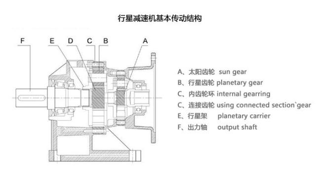
A, sun gear sun gear
B. Planetary gear (combined with planet carrier) planetary gear
C, internal gearring
C. Connecting gear using connected section`gear
E, planetary carrier
F. output shaft
The driving source starts the sun gear in a direct connection or connection mode, and the sun gear drives the planetary gear combined on the planet carrier to run.The entire planetary gear system rotates automatically along the outer gear ring, and the planet carrier is connected to the output shaft to achieve the purpose of deceleration.The higher reduction ratio is accumulated by multiplying multiple sets of stage gears and planetary gears.
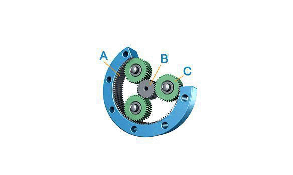
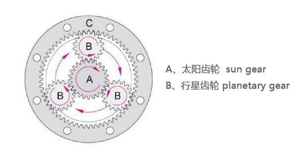
The planetary reducer is tightly combined with an inner gear ring (A) on the gearbox housing. The center of the ring gear has a sun gear (B) driven by external power. Between the two, there is a set of three gears equally divided. The planetary gear set (C) assembled on the tray. This set of planetary gears relies on the output shaft, the inner gear ring and the sun gear to support the floating during the period; when the input side power drives the sun gear, it can drive the planetary gear to rotate and follow The track of the gear ring revolves along the center, and the rotation of the planet drives the output shaft connected to the tray to output power.
Disassembly and assembly steps of planetary gear reducer bai:
1. Confirm the specifications of the du motor and reducer, and wipe the mounting surface of the motor and reducer clean.
2. Take out the two black dust caps from the body.
3. Remove the original key on the motor; if necessary, Bapman recommends installing a balance key.
4. Confirm the size of the motor shaft, and if necessary, install the shaft bushing. (When the motor is in the shape of a flat shaft, align the gap between the shaft and the center line of the flat shaft so that the locking hub screw is perpendicular to the shaft.)
5. Install the motor upright, use 5% of the recommended torque value in the screw torque table, in the order of 1-4, and use a wrench to lightly lock the screw with the washer.
6. For the torque value recommended by the parameter, use a wrench to tighten the 2 screws on the locking ring forcefully.
7. Place the motor and reducer upright, and tighten the screws with a torque wrench in the order of 1-4 according to the torque value suggested by the screw torque table.
8. Put the 2 black dust caps on again.
Recommended
- The effect of loose connection bolts 2019-12-11
- Plum blossom coupling size and model 2019-12-09
- The correct way to maintain the coupling of transmission parts 2019-12-09
- Installation, disassembly and maintenance of universal coupling 2019-11-30
- Universal coupling connection and basic principles 2019-10-09